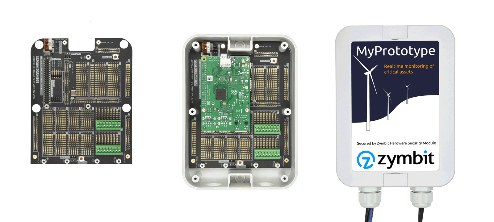
ProtoKit5
SECURE PROTOKIT FOR Pi COMPUTERS
Waterproof, Dustproof, Radio Transparent, Tamper Evident.
Upgraded Features
ProtoKit5 replaces the ProtoKit4. We had a lot of great feedback from customers of our earlier ProtoKit 4. Here are some of the improvements we made:
- Larger IP67 enclosure: W x H x D | 130 x 175 x 45 mm | 5.12 x 3.24 x 1.77 inches
- Two cable glands
- All components soldered to board, ready to go.
- Fully integrated tamper detect perimeter circuits - switch, pads, user defined.
- Easier to wire, more robust connectors - screwless, spring cage & tension clamp.
- Dedicated +5V connector
- Schematics
- How to wire
What’s Inside Your Kit
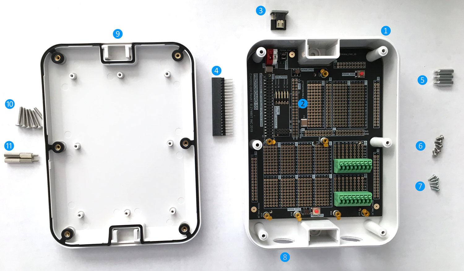
This kit comes assembled and ready to start building your prototype in to. The following components are included:
❶ IP67 enclosure, dustproof, waterproof enclosure with lid
❷ Integrated protoboard.
❸ Adapter for perimeter circuits
❹ GPIO connector extension
❺ Standoffs for Pi, M2.5 - x 3
❻ Screws for Pi, M2,5 Torx T8 - x 3
❼ Screws for protoboard fix - x5
❽ Cable glands, 3/4 - x2
❾ IP67 lid with neoprene gasket
❿ Screws for lid - x6
⓫ Tamper switch actuators - x2
BUY NOW >
A TOUR OF THE PROTOBOARD
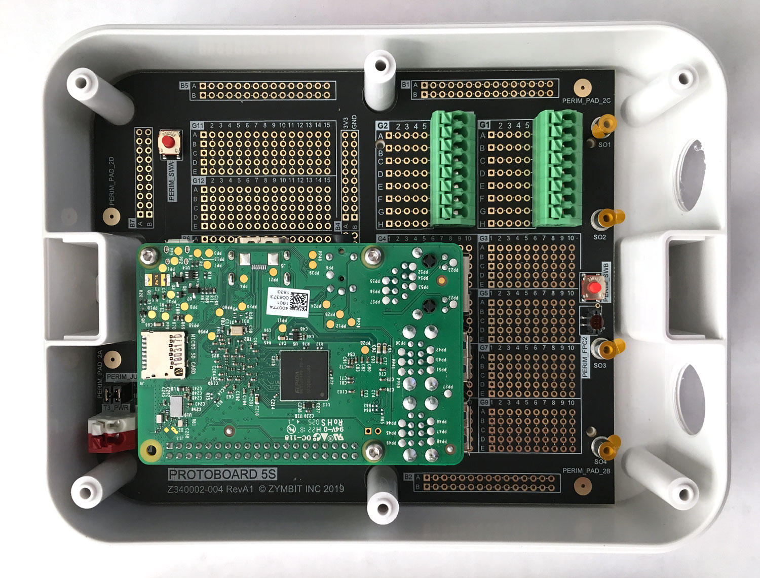
The protoboard fits cleaning into the enclosure and can easily be removed for wiring and assembly with your components.
Slot for Pi Computer
Protokit will fit the following Pi footprint computers:
- Raspberry Pi 2, 3, 3B+, Zero
- Asus Tinkerboard
- Odroid C2 (Heatsink may interfer if zymbit security module fitted)
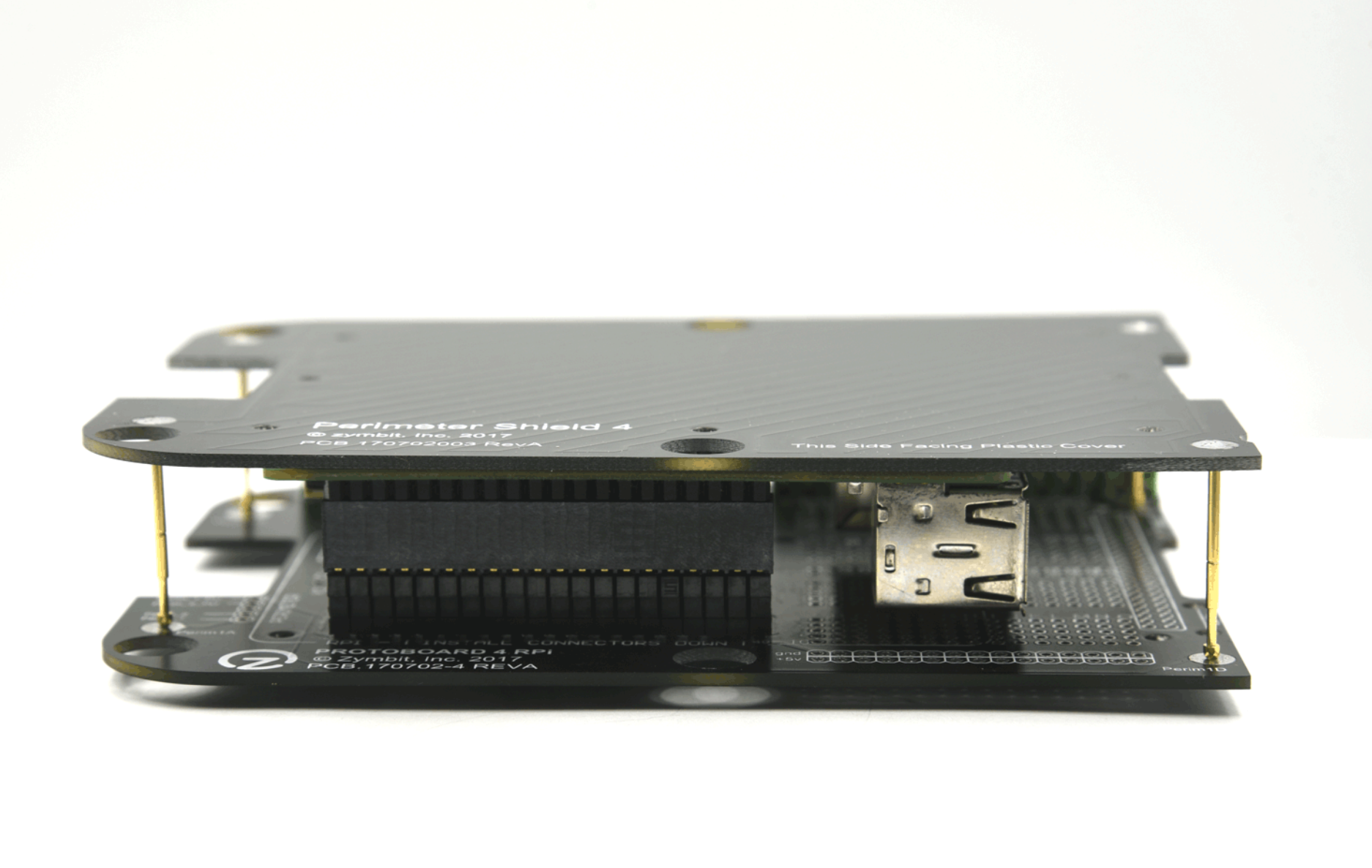
IMPORTANT ! - The Pi computer is fitted connector down, with the CPU facing the protoboard.
Standoffs to Mount Pi Computer
Three M2.5, 5mm pcb standoffs are soldered to the board. Additional screw-in standoffs are supplied to achieve an overal standoff - between Pi and protoboard - of 18mm.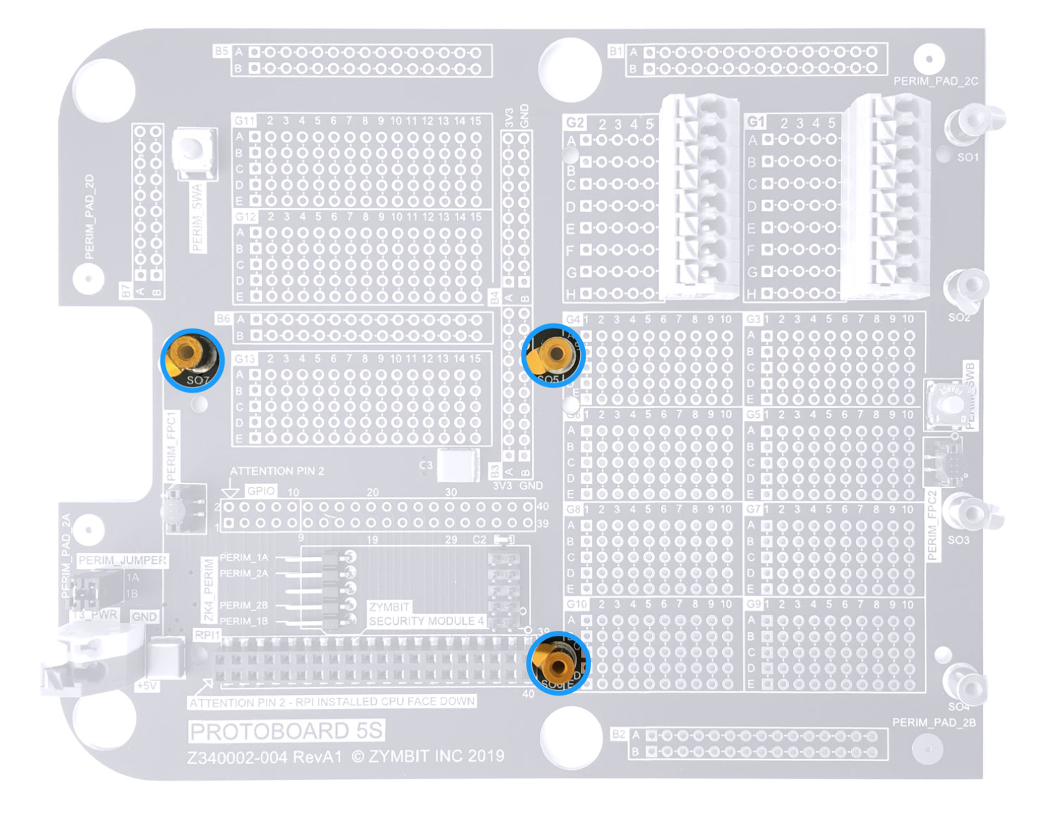
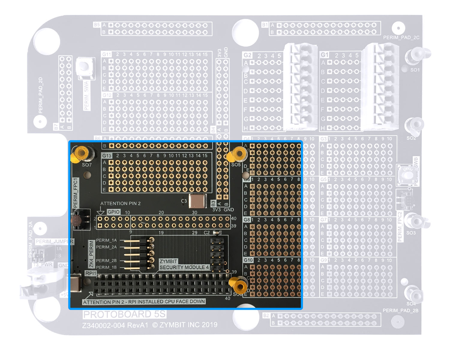
Slot for Zymbit Security Module - Zymkey 4i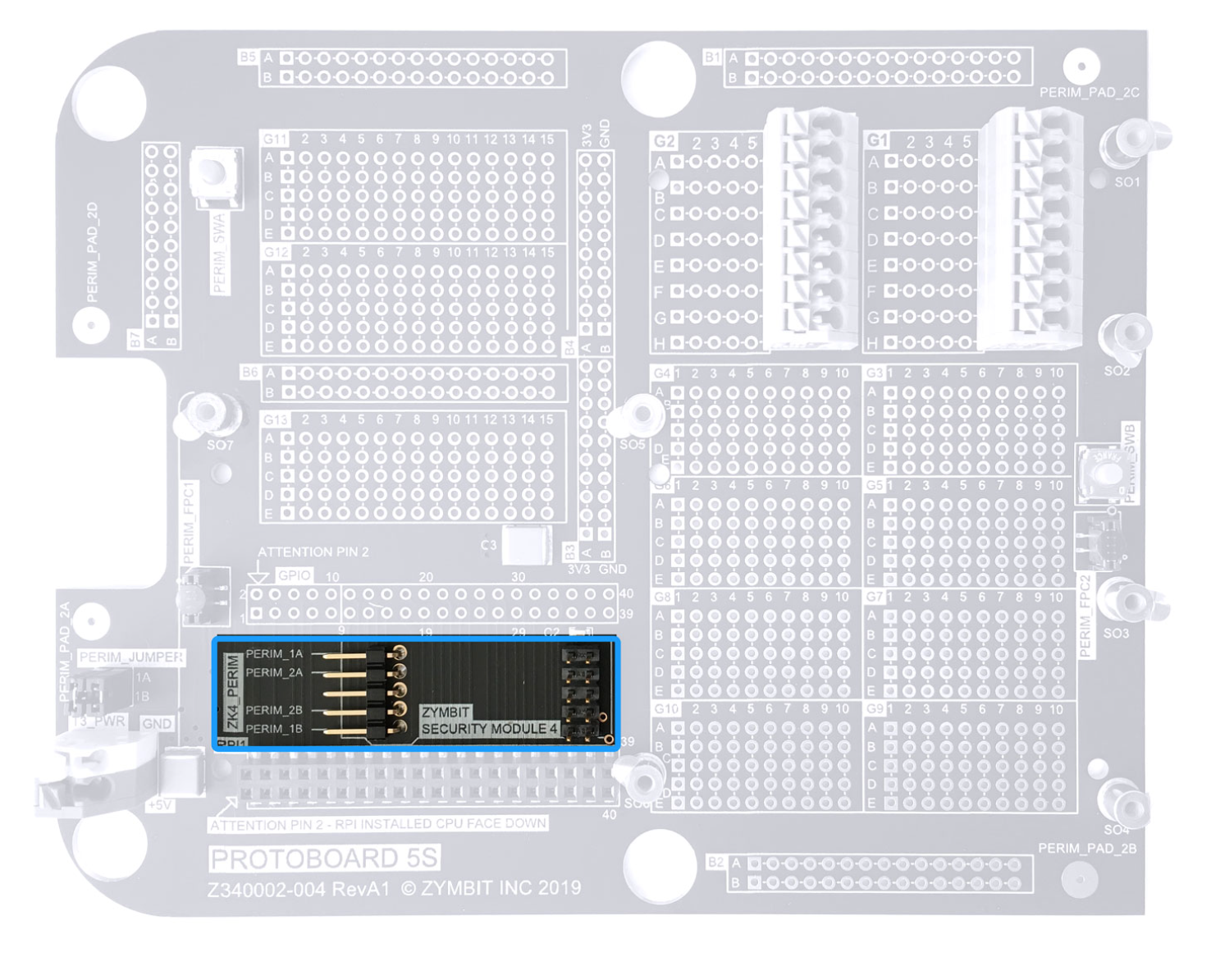
Perimeter Adapter Interface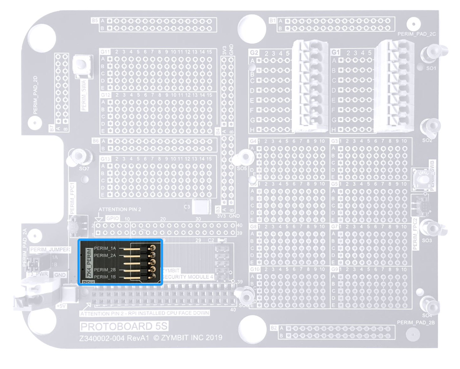
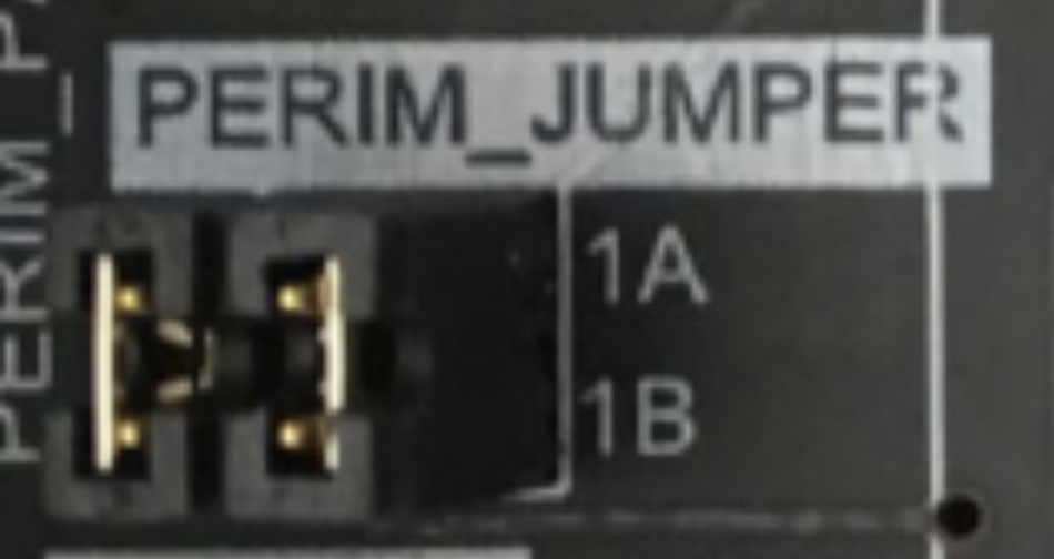
Perimeter Configuration Jumper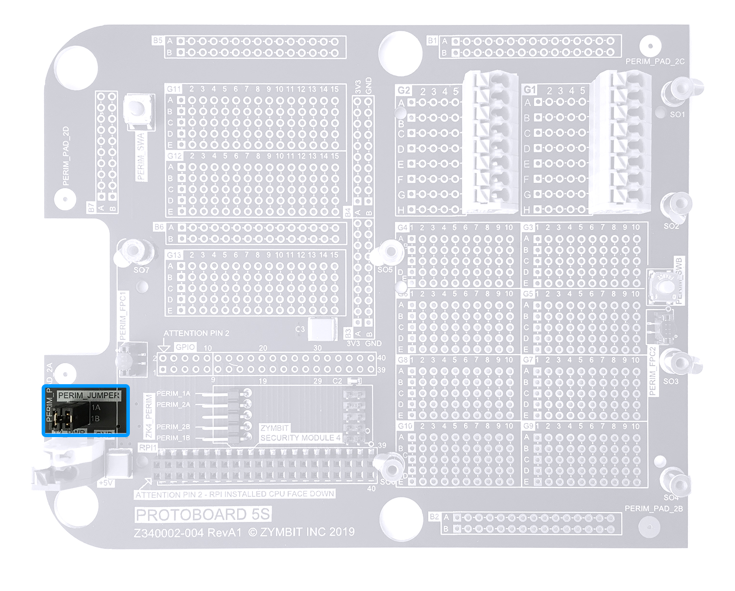
Tamper Switches - Circuit 1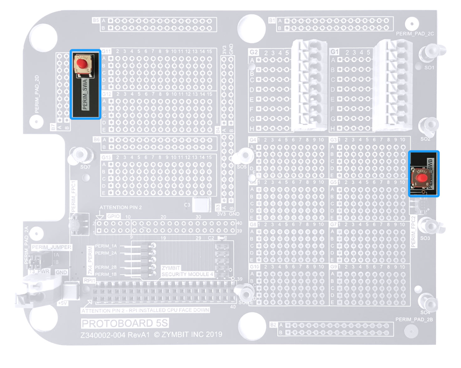
Perimeter Pads - Circuit 2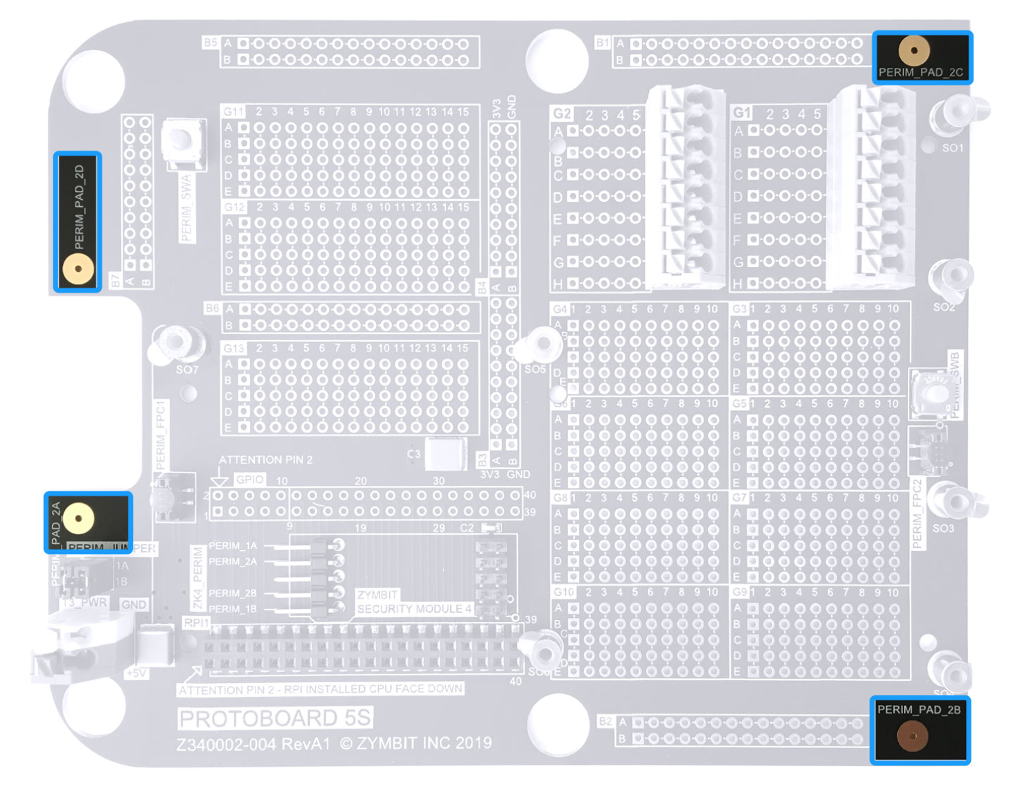
Input / Output Connectors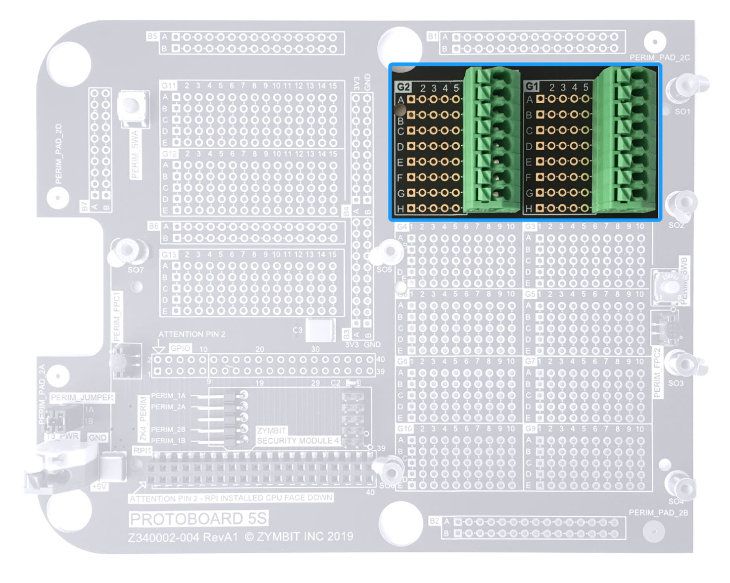
+5V Power Input Connector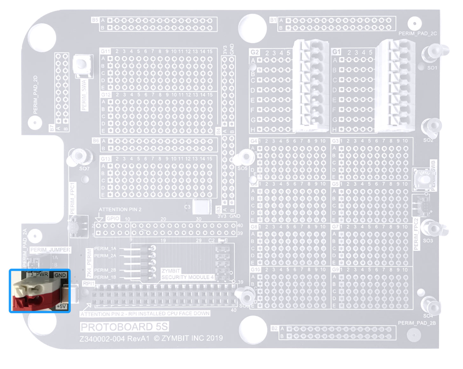
Power Bus - 3v3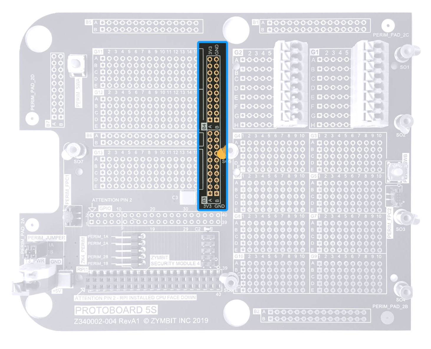
Bus Bars - 2 X 15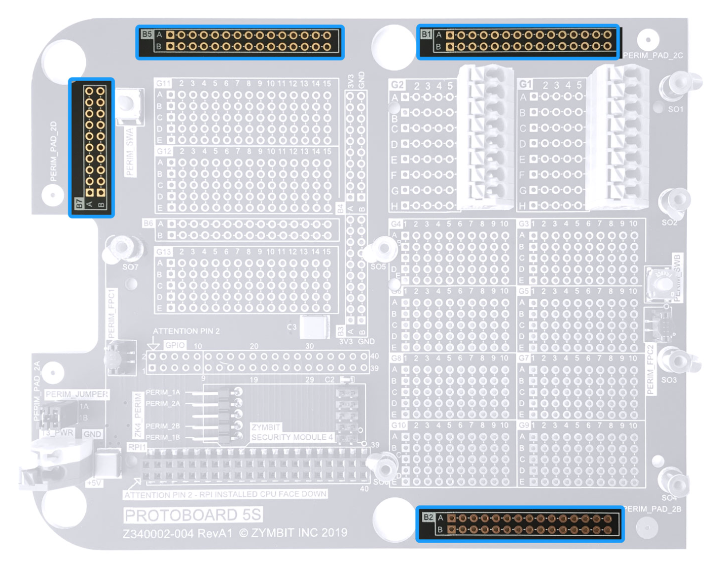
Grid Arrays - 5 X 15
The grids are not powered and are designed to make it convient to solder wires and components into your design.
The reference markers make it easy to document your design and later transfer to work instructions or a PCB design net list. Each pad can be uniquely referenced as G15.D.9 for example.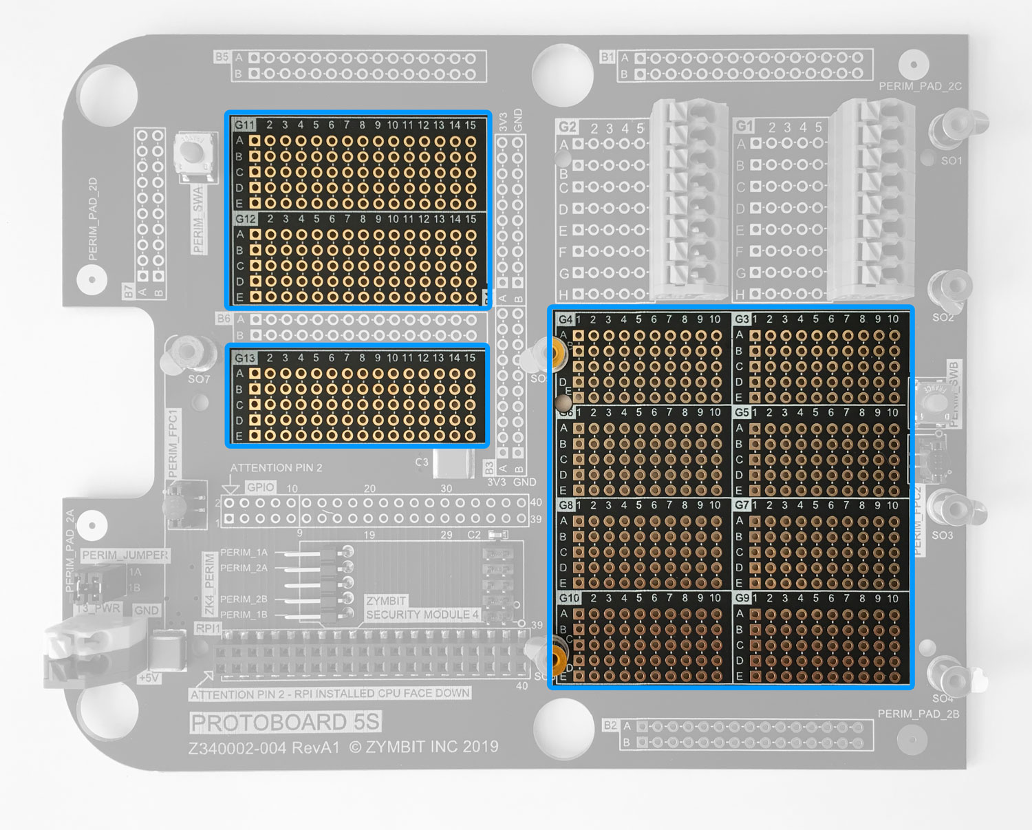
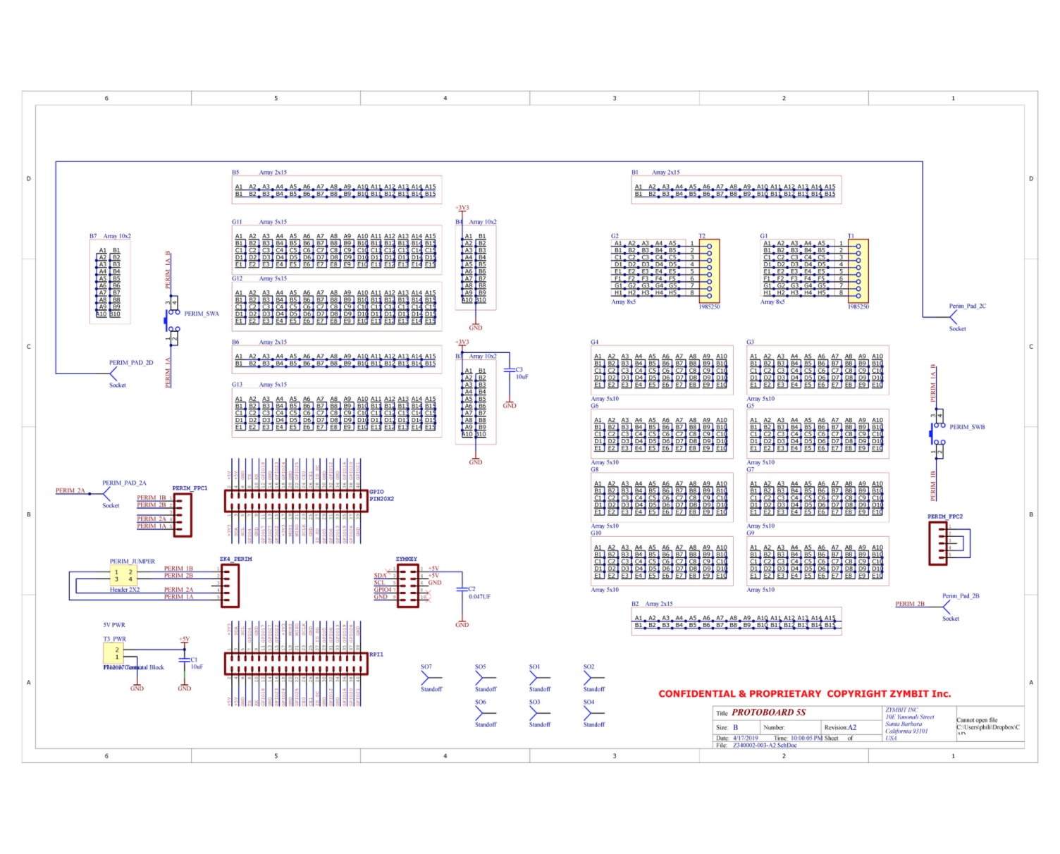
Schematic of Protoboard Download Schematic >
ASSEMBLING YOUR PROTOKIT 5S
Fitting a Zymbit Security Module & Perimeter Adapter
If you are fitting a Zymbit security module, here’s where it goes. Fit the perimeter adapter at the same time.
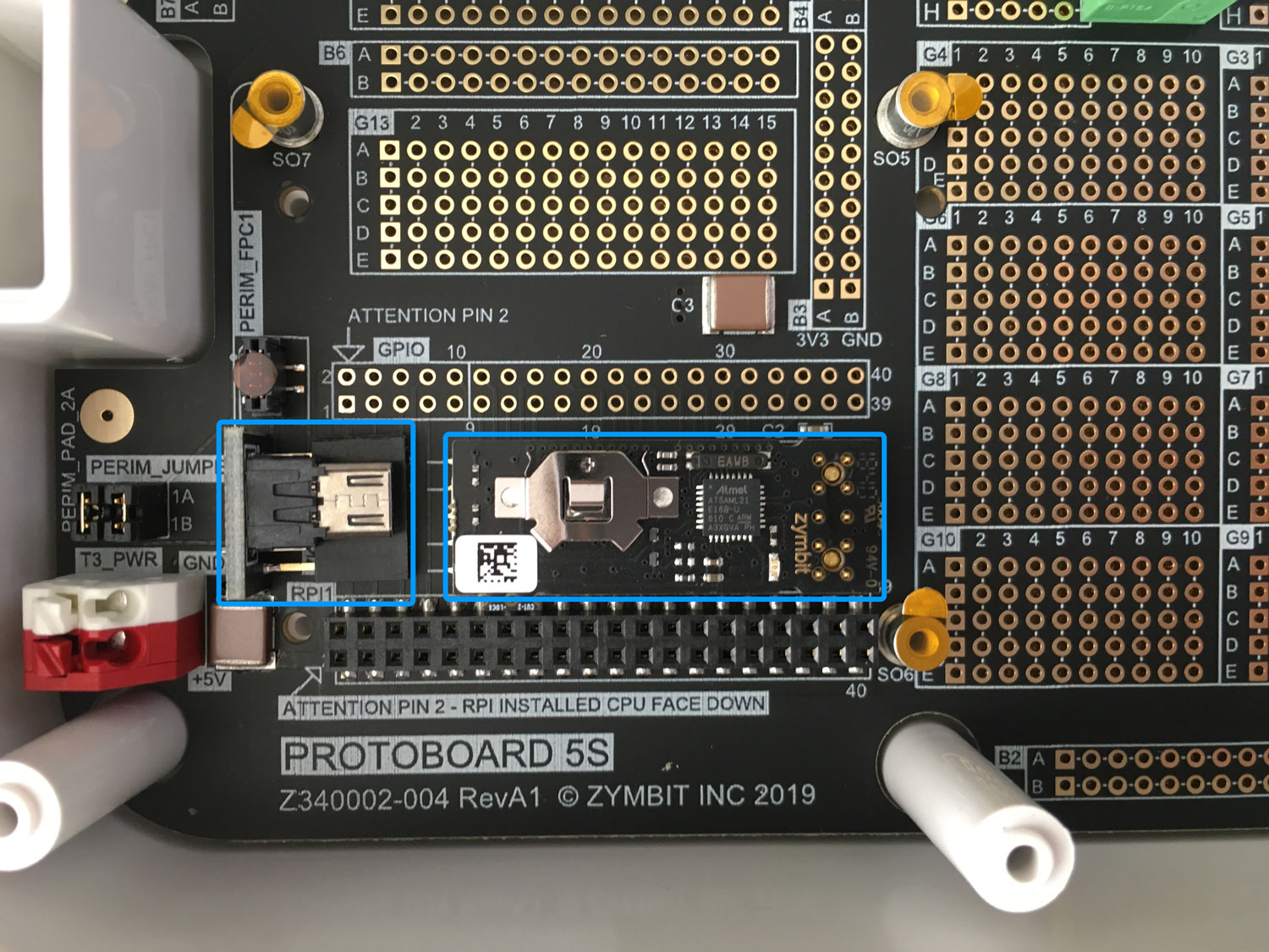
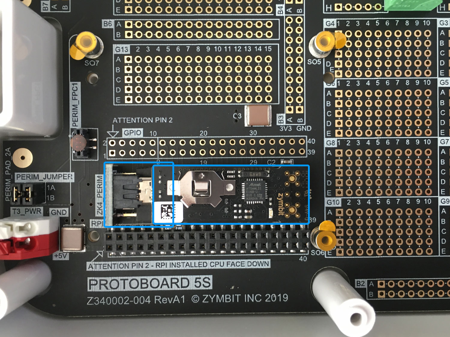
Sequence for Fitting Zymkey4 and Perimeter Adapter
Configuring Perimeter Detect Circuits
Zymbit security modules contain two perimeter circuits that can be used to detect tampering of a secure envelope. Each tamper circuit is closed in normal operation. When a circuit is opened, a Tamper Event is registered by the Zymbit Security Module.
Learn how to configure and operate perimeter events in software >
Typically the two circuits are configured to provide independent layers of physical security:
- PERIM 1 - protects an inner electronic enclosure, like this ProtoKit5 enclosure.
- PERIM 2 - protects an outer cabinet enclosure, trip wire or other.
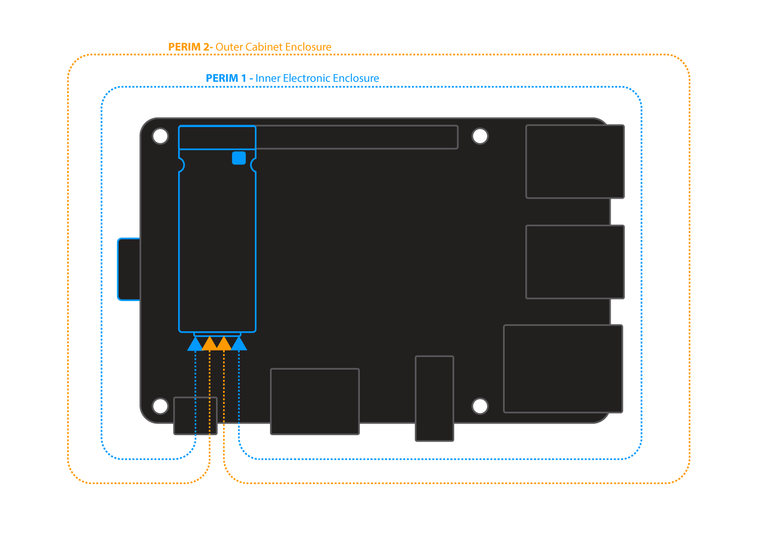
On ProtoKit 5 there are several ways to configure PERIM 1 and PERIM 2. By default both circuits are closed with two jumpers. 1A<>1B , 2A<>2B.
Using Tamper Switches
The protoboard includes two tamper switches, PERIM_SWA and PERIM_SWB, that are connected in series to the PERIM 1 tamper circuit. To configure and activate these switches follow these steps:
- Remove the Jumper 1A<>1B
- Pressing down both switches SWA, SWB will close the PERIM 1 circuit.
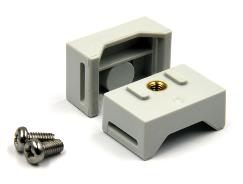
- The lid of you ProtoKit 5 includes two “actuators” that align with the switches and activate (close) them when the lid is fitted and screwed securely in place. If needed you can adjust the length by screwing the actuator in or our of the panel.
Tamper Switch Actuators Fitted to Lid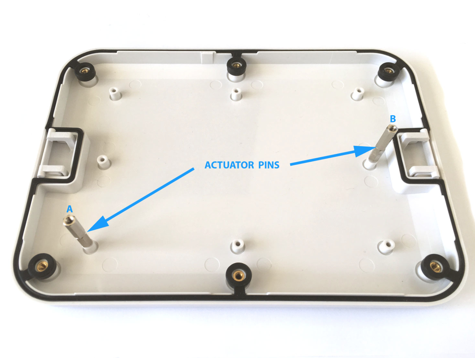
Tamper Switch Actuators Pressing Switches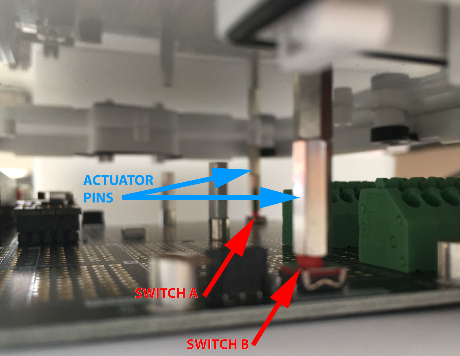
Using Perimeter Pads
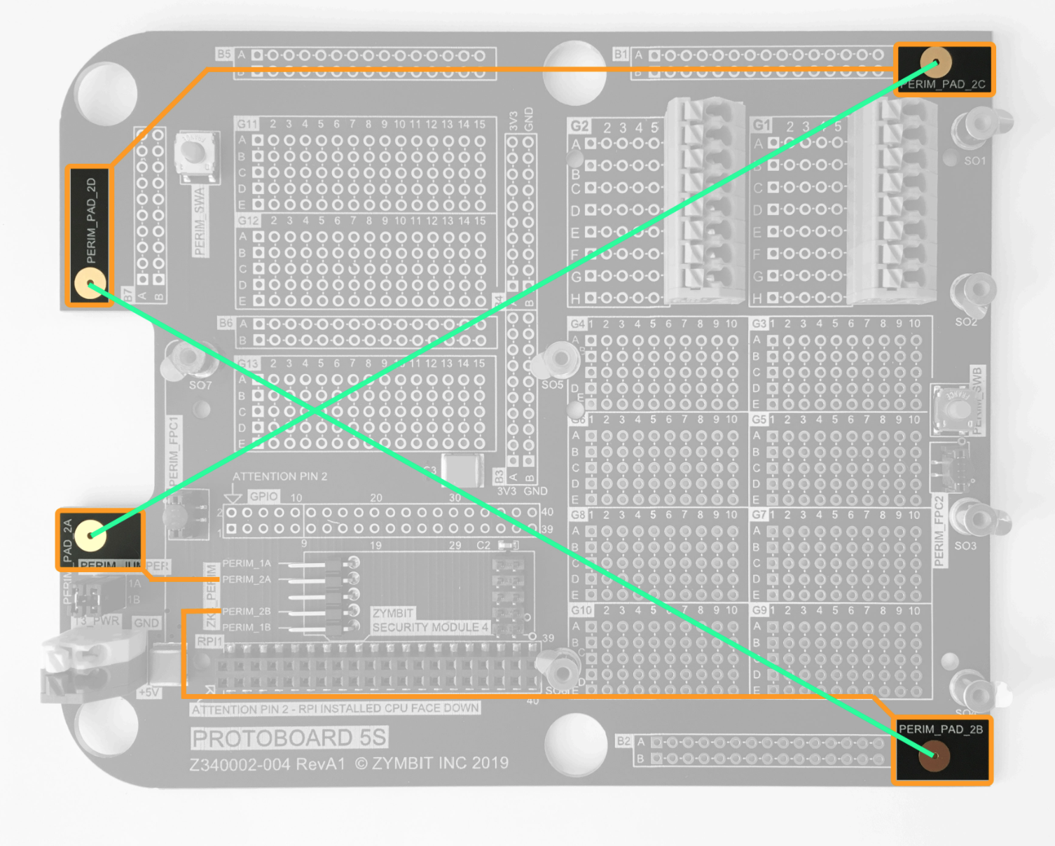
The protoboard includes four tamper pads that are connected to the PERIM 2 tamper circuit as follows:
Connected on protoboard PCB (orange color) PERIM_PAD_2A <> PERIM_2A_ZYMKEY4 PERIM_PAD_2B <> PERIM_2B_ZYMKEY4 PERIM_PAD_2C <> PERIM_PAD_2D
Connected by user circuit (green color) PERIM_PAD_2A <> PERIM_PAD_2C PERIM_PAD_2B <> PERIM_PAD_2D
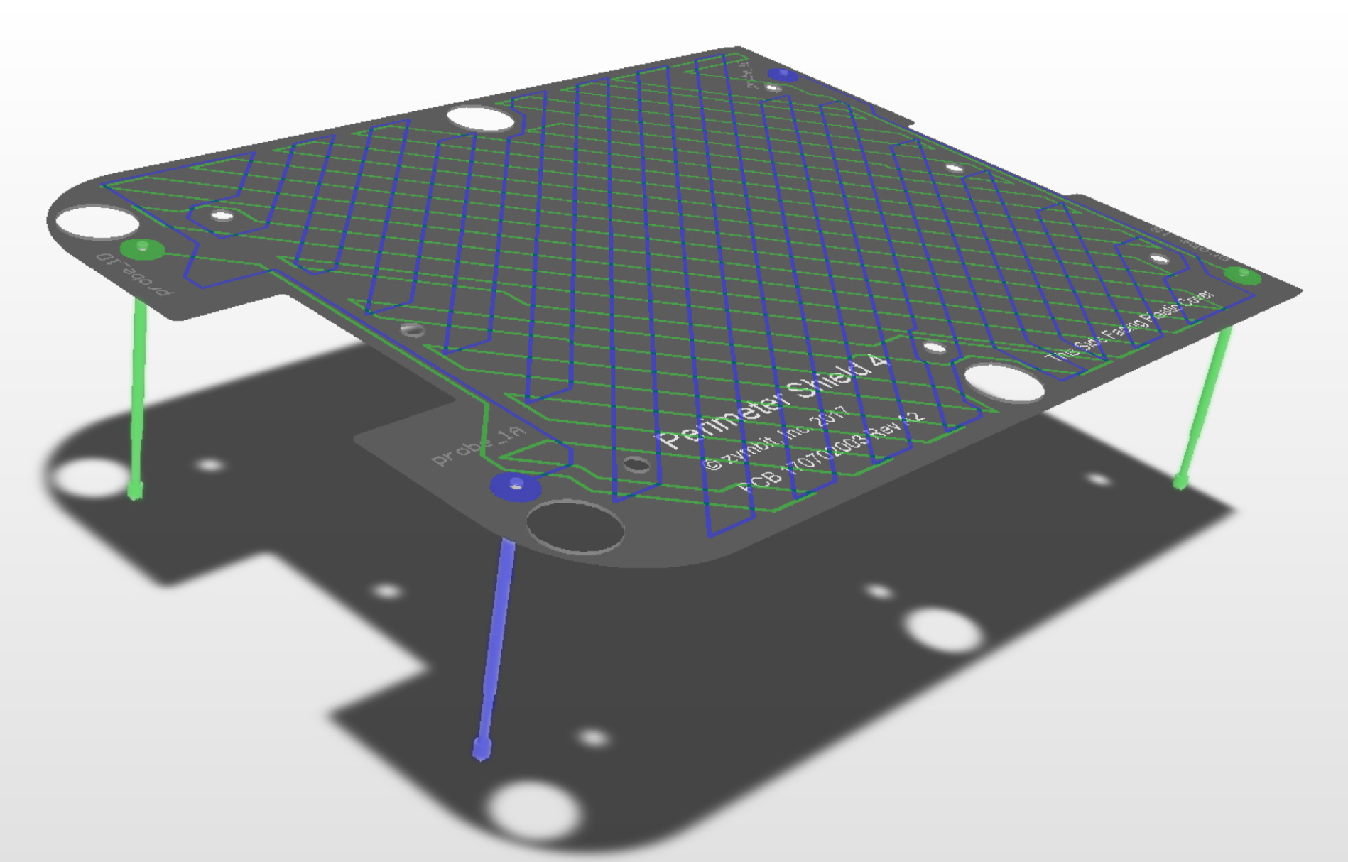
Examples for Using Perimeter Pads The Perimeter Pads are designed to be used in applications where the lid contains a user defined circuit such as a display or keypad, or this custom shield (which was designed for ProtoKit4). Springed Pogo pins can be used to connect the lid to the perimeter pads. This provides an additional layer of physical security to the tamper-switches.
Add Your Pi Computer
Fit the GPIO extender header.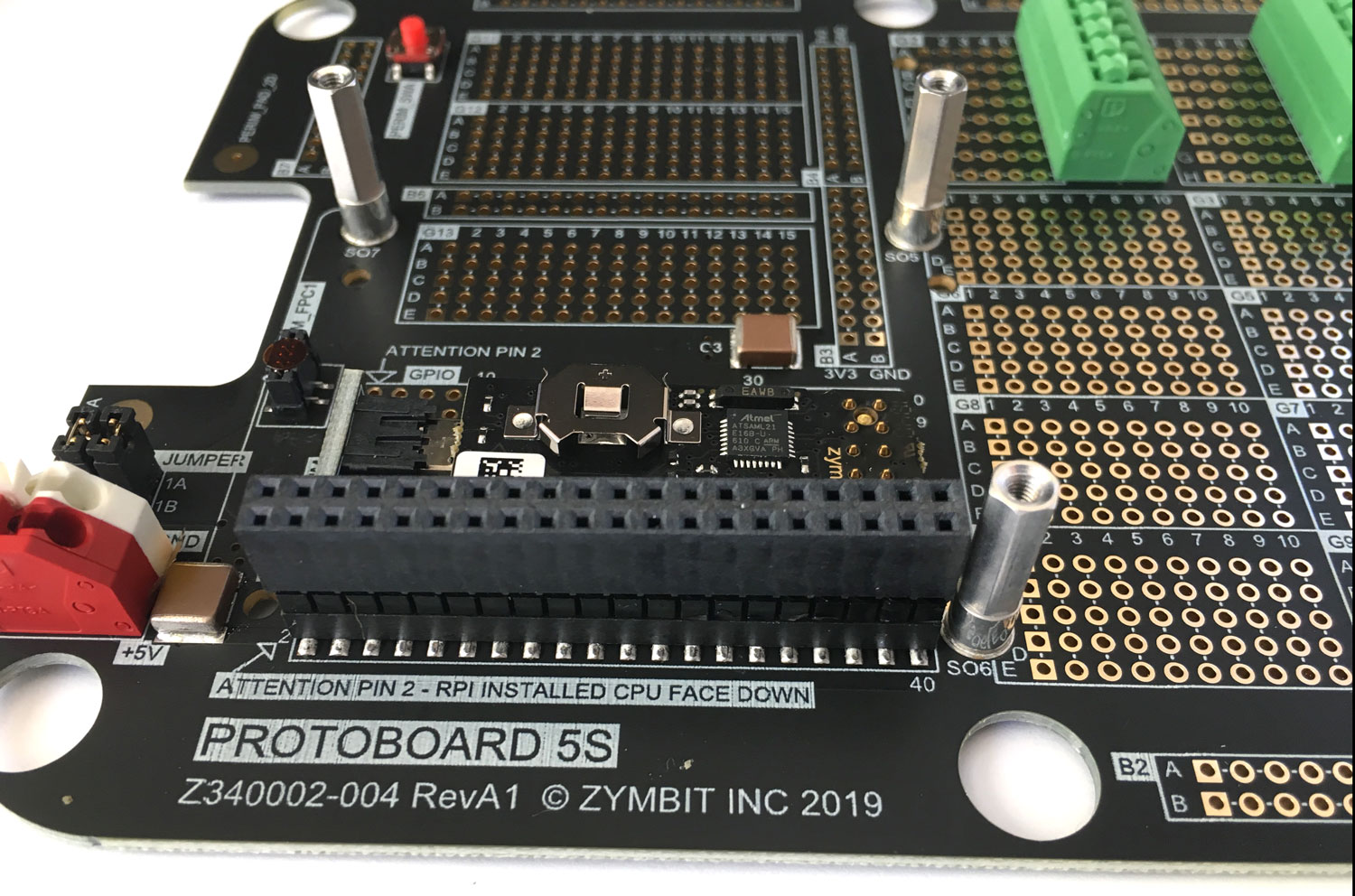
Fit your Pi computer being careful to correctly align pins. Secure in place with three M2.5 screws using a T8 TORX driver.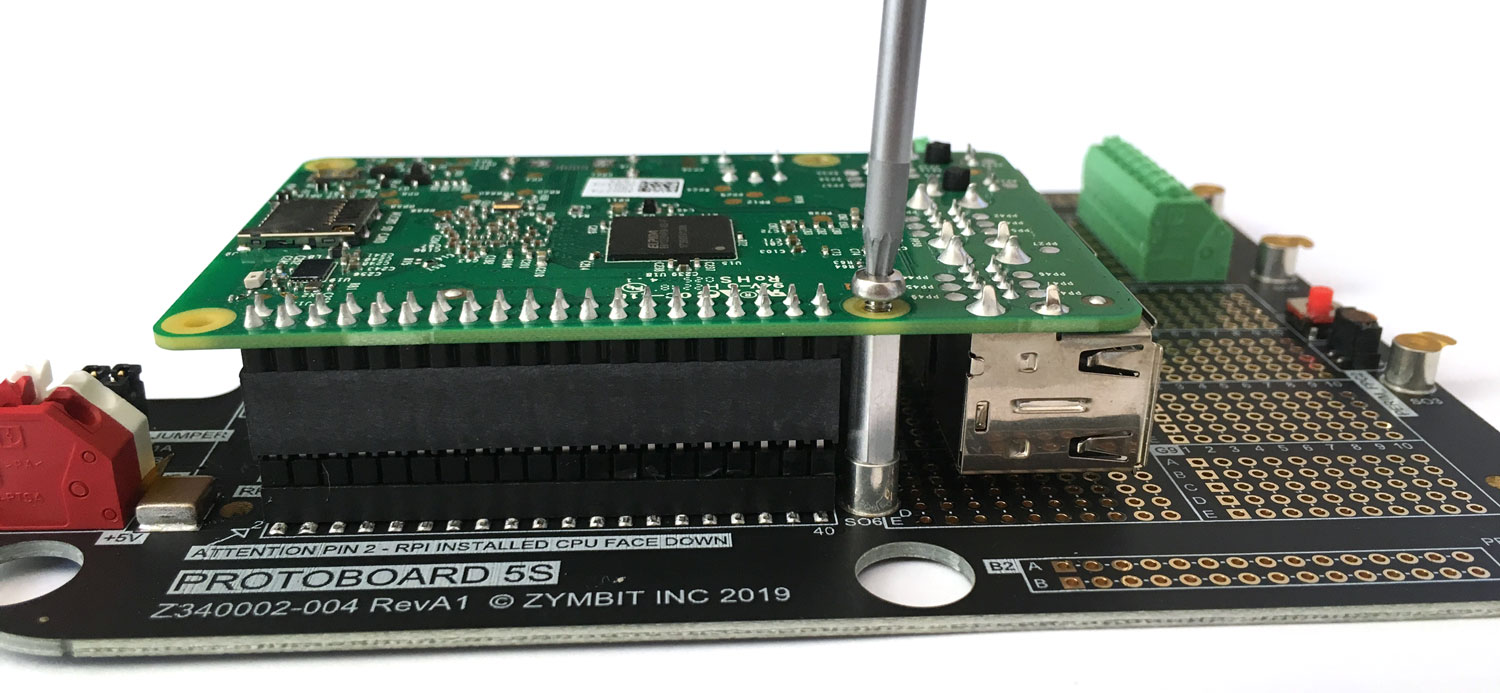
Place into Enclosure
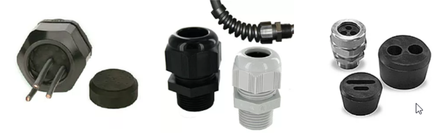
Fitting Cable Glands
Your kit comes with two nylon cable glands pre-fitted into ½" 14 NPT threaded holes. They accept cables with diameter 0.51" to 0.71".
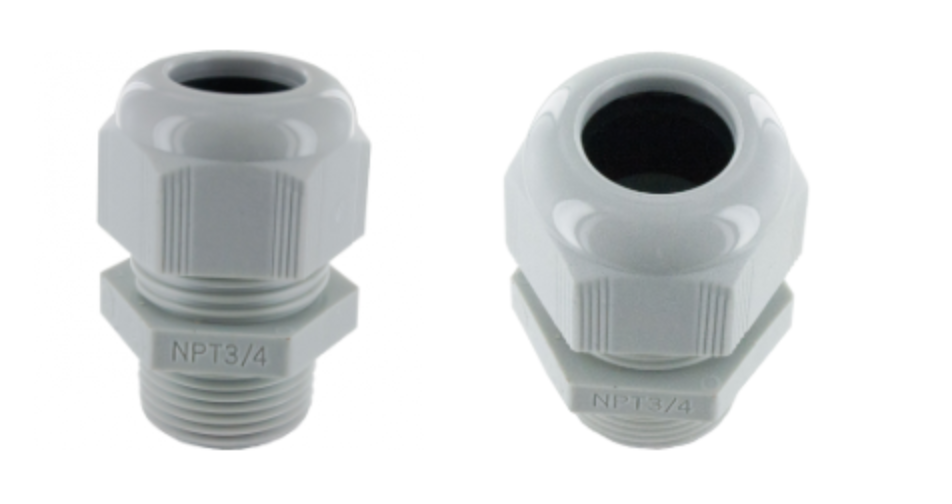
Need something different? There a many different types of cable glands: size, cable clamp, strain relief, number of cables, material, etc. If you need something different to what is supplied with you kit, then check out this supplier who has a great selection. ElecDirect >
Add Enclosure Lid
Be sure to add the black seal that was provided with your kit.
IP67 Enclosure Ratings
The enclosure is rated for the following ingress protection.
IP6x Solid particle protection
- Dust Tight - complete protection against contact (dust tight). A vacuum must be applied. Test duration of up to 8 hours based on air flow.
IPx7 Liquid ingress protection
- Immersion, up to 1 m depth. Ingress of water in harmful quantity shall not be possible when the enclosure is immersed in water under defined conditions of pressure and time (up to 1 m of submersion).
For further details on IP ratings refer to wiki/IP_Code.
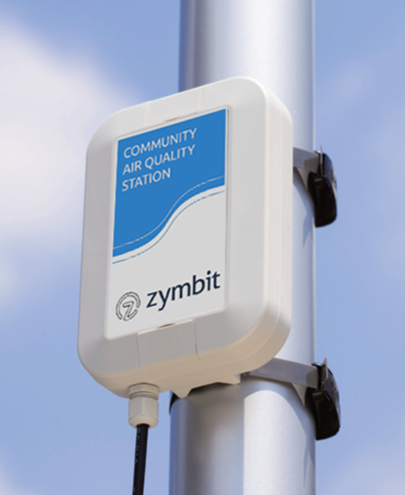
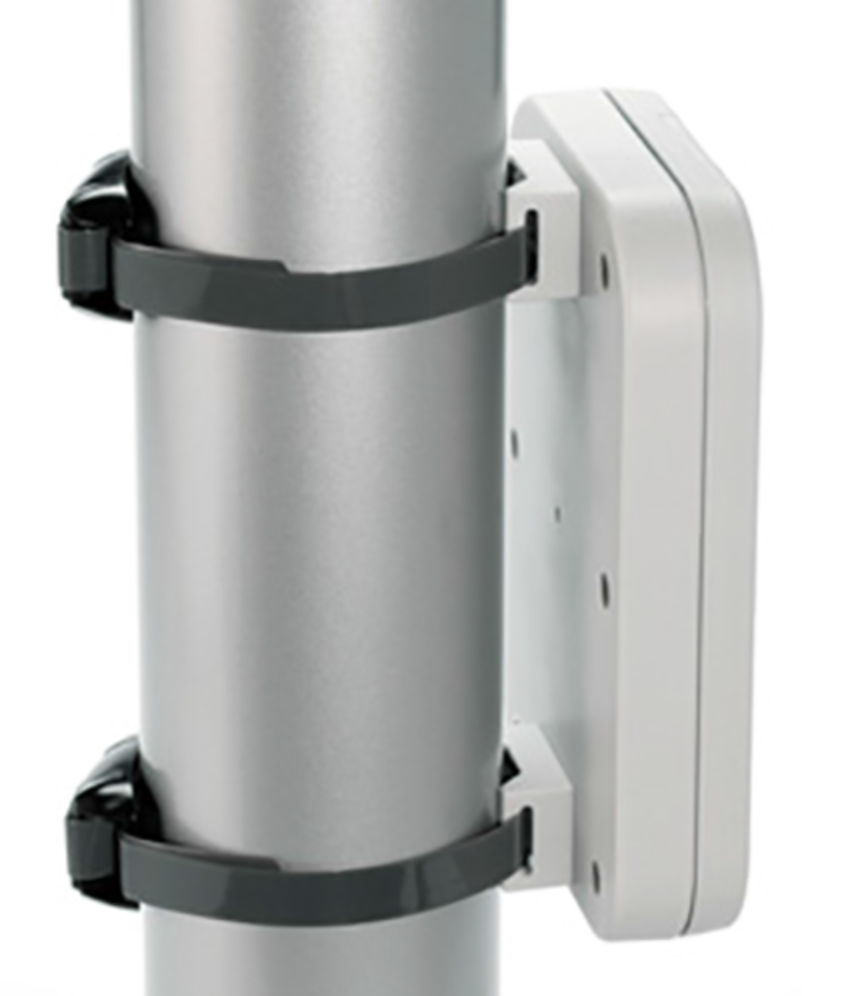
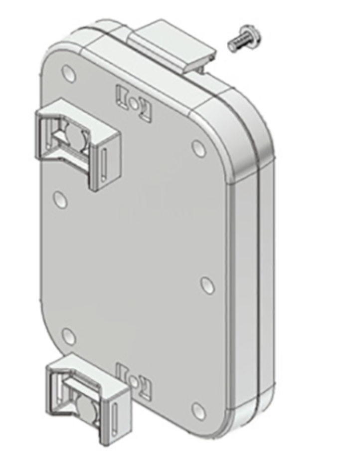
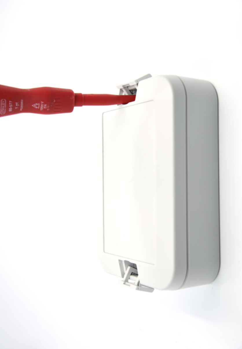
MOUNTING OPTIONS
Panel Mounting This enclosure can be mounted directly to a wall or flat surface using two self tapping screws.
Pole Mounting This enclosure can be easily mounted to a pole using a pole mounting brackets available from the Zymbit store.