ZYMKEY5 CAD Files, Connectors, and Pinouts
3D Step Model
Auxiliary Connector
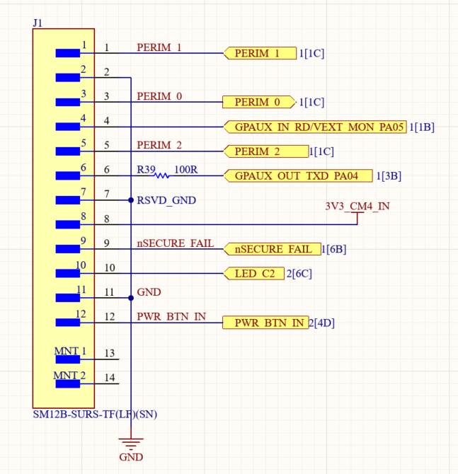
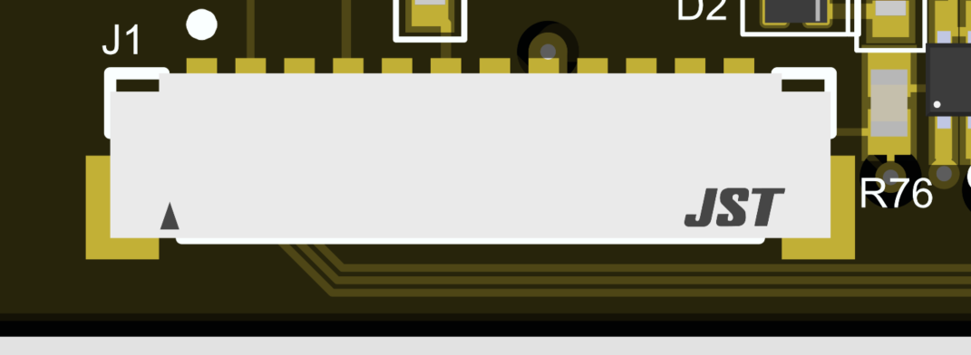
12 pin JST SURS connector (SM12B-SURS-TF(LF)(SN))
Mates with 12SUR-32S (premade cable harnesses)
Pins 1, 3, and 5 carry the perimeter tamper loops. To wire and test them, see Perimeter Detect: Zymkey5.
| Pin Number | Pin Name | Description |
|---|---|---|
| 1 | PERIM_1 | Tamper detection loop 1 receive |
| 2 | GND | System ground |
| 3 | PERIM_0 | Tamper detection transmit. Connect this pin to PERIM_1 and/or PERIM_2 |
| 4 | GPAUX/VEXT MON | Auxiliary input (digital or analog, 1k R in series) |
| 5 | PERIM_2 | Tamper detection loop 2 receive |
| 6 | GPAUX_OUT | Auxiliary output (digital, 100ohm R in series) |
| 7 | RSVD_GND | Ground pin do not use (reserved) |
| 8 | 3V3 | 3.3V output from Zymkey voltage regulator. Powered from 5V, on when Pi is shut down |
| 9 | nSECURE_FAIL | Open drain security fault indicator; 12V max |
| 10 | nLED_OUT | Open drain blue LED indicator; 12V max |
| 11 | GND | System ground |
| 12 | nSEC_BTN_IN | Secure button input. 3.3V max. Connect between the pin and ground |
A. AUX I/O pins 4 and 6 are supported on certain firmware releases only. Contact Zymbit for more details.
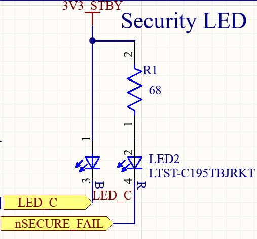
B. CAUTION: 3V3 pin 8 is the direct output from the voltage regulator on Zymkey. This regulator is completely separate from the 3.3V supply on the host and is powered from the 5V pin on the 10-pin host connector. Avoid drawing more than 10mA of current. Avoid shorting the pin or back-feeding voltage into the pin. Avoid connecting the output of this pin to host I/O pins as doing so may back-power the host when its 3.3V power is off and may cause a latch-up and/or hardware damage. The 3V3 pin is intended for LEDs and for low power / sleep mode operation only. This pin may be used to power the SECURE_FAIL LED or the remote blue security status LED, for example (see below). Failure to follow these instructions may cause damage to both Zymkey and the host.
C. Tamper detection pins (pins 1, 3, 5): PERIM_0 is the transmit line and PERIM_1/PERIM_2 are the receive lines. NOTE: Zymkey 5 perimeter circuit is more advanced as compared to Zymkey 4 circuit. Connecting PERIM_0 to either of the RX lines PERIM_1/PERIM_2 completes the respective tamper loop. The tamper loop uses a high-entropy encoded pulse train with circuit delay measurement. Caution: do not connect tamper loop pins to any other voltage source or system ground. When the system is powered off and the battery is installed, the tamper loop is powered from the coin cell battery. Avoid creating current leakage in the loop as that may reduce battery life. Do not power LEDs from the loop.
D. nSECURE_FAIL pin 9: open collector output that is pulled low when a hard security failure has occurred, or self-destruct was triggered (certain scenarios). 12V max pull-up voltage, 20mA max current. The output may activate briefly when the device is in coin-cell backup mode (no 5V power). This is due to the low power nature of battery operation, as the internal circuit on Zymkey is fail-safe (i.e. generic hardware or Zymkey CPU failures will cause the output to be active). The pin may also activate for a short period of time when power is turned on/off and when Zymkey reboots internally. >2sec activation of nSECURE_FAIL with full power applied to the 5V rail may be used to definitively establish the failure.
E. nLED_OUT pin 10: open collector output that is pulled low when the blue LED on Zymkey is on. 12V max pull-up voltage, 20mA max current. Please see
F. nSEC_BTN_IN pin 12: secure button input. Install button between this pin and ground. Drive to 0 to activate. Supported on certain firmware releases only. Contact Zymbit for more details.
Breakout Board / Cable
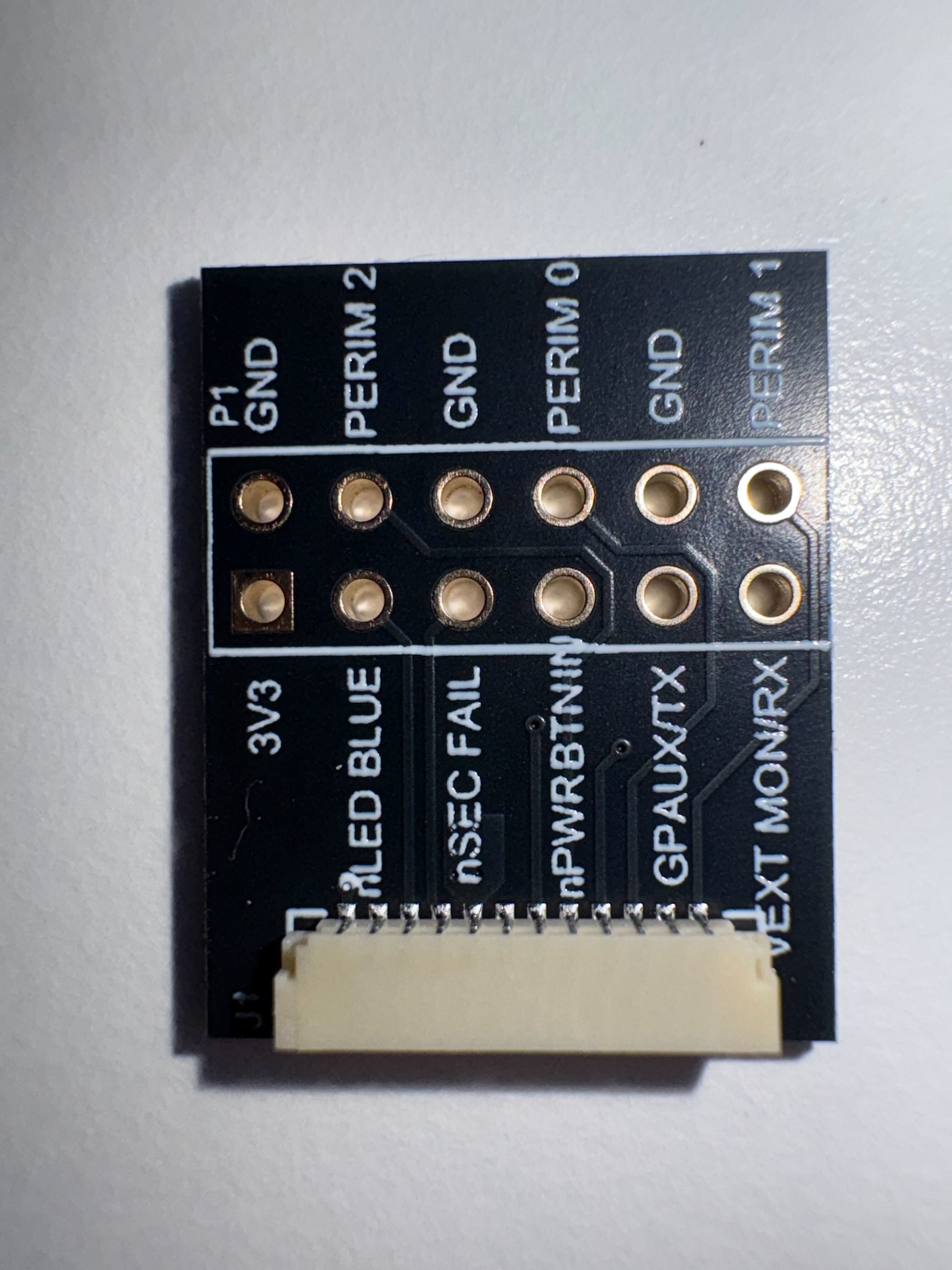
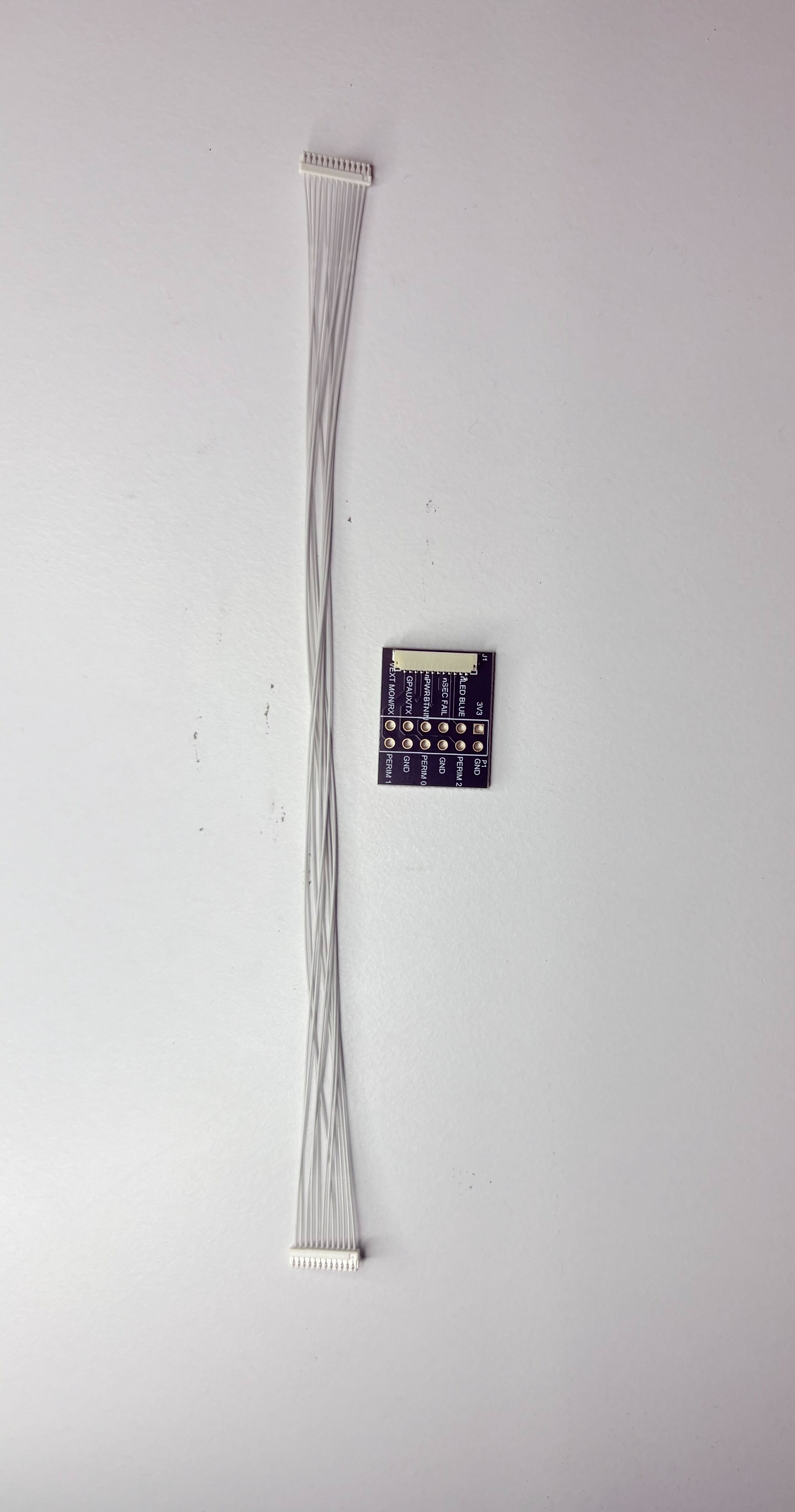
Zymbit makes a breakout cable that exposes the pins of the Auxiliary connector. Use one of the premade cable harnesses to connect to the breakout board. The pins are labeled according to their function and are laid out in a way that is intuitive for use, not in order of pin number! Use the pin descriptions above to identify how each pin operates.
LED Example
Battery Connector
JST SM02B-SRSS-TB(LF)(SN)
Pin 1: GND
Pin 2: VBAT+
Mates with housings with 02SR-3S or similar headers. This is the same battery connector that is on the Pi5. It takes 3.3V batteries (like the Pi5 battery) and is used to power the RTC on the ZYMKEY5.
BATT CHRG Pads
Battery charging is an option on Zymkey5. Please contact Zymbit for more details. For pre-production Zymkey5 (rev -A1 mark on the PCB) – DO NOT USE, may cause battery drainage.
GPIO Pinout
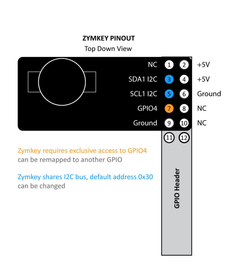
Same as Zymkey4.