Secure Edge Node - SEN 500
Introduction
The SEN 500 provides all the hardware and software components required to get started implementing your secure application. Inside, the SEN 500 includes a Raspberry PI CM5, the Zymbit Secure Base Board, and the HSM65 security module, detailed below.

Specifications
Configure and Setup your SEN 500
Quickstart
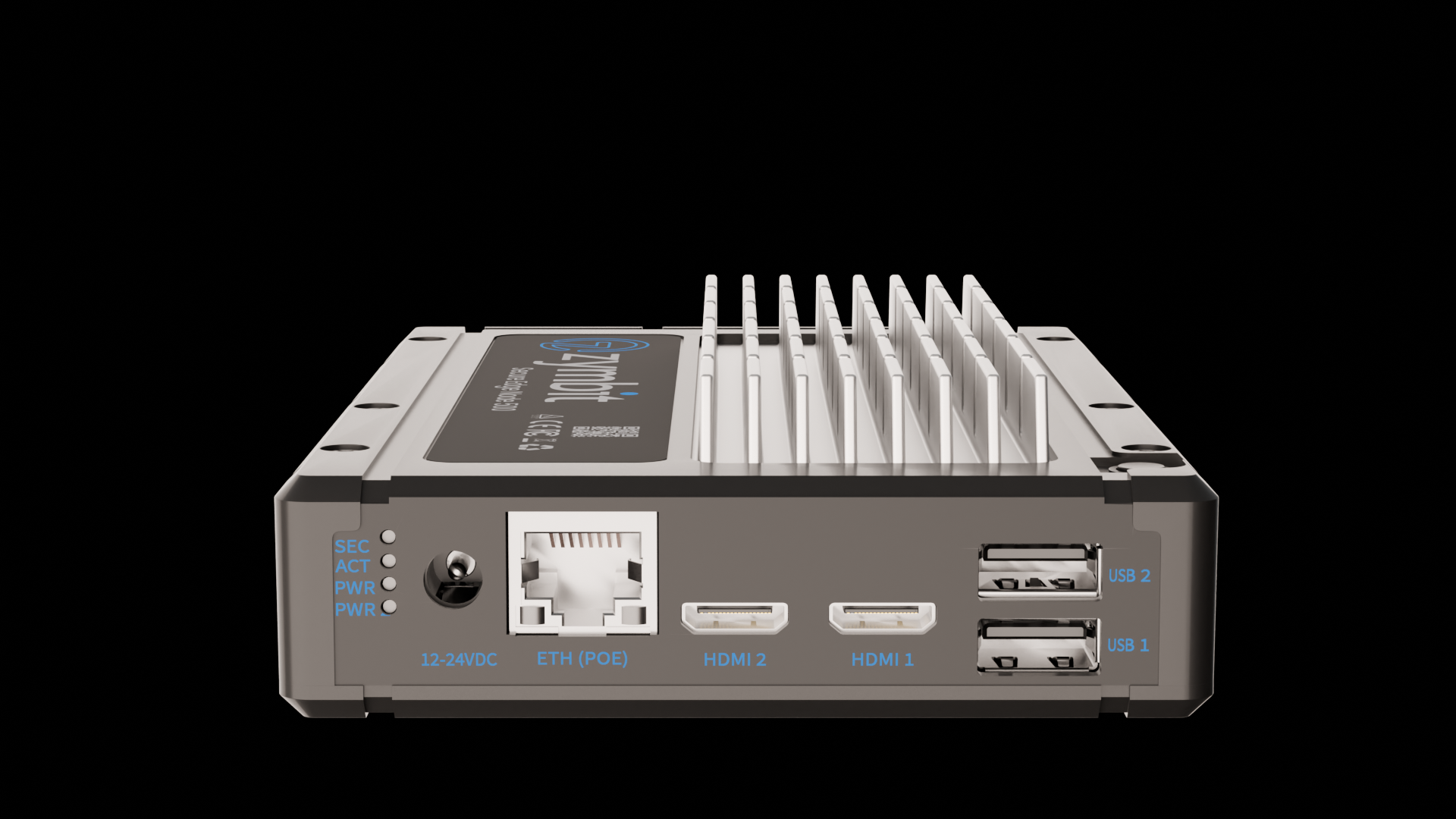
- Connect the 12-24V Power Supply up to the front panel barrel connector.
- Connect an Cat5e/Cat6 ethernet cable to the gigabit ethernet port.
- The unit is designed to run either headless via SSH, or, if you prefer, attach a monitor to one of the HDMI ports and a keyboard and mouse to the USB ports and login via the console.
- Monitor the top LED (SEC) for the status of the Zymbit module. It will go through the following stages:
- rapid blue blinking: Booting underway
- one blue blink every 3 seconds: zkifc has loaded and the system is ready to go
- Once the boot sequence completes and the top LED (SEC) is blinking blue once every three seconds, login either via the console or remotely via SSH. As shipped, the hostname is
zymbit-devand a user namedzymbitcan be used for login. The default password iszymbit. Please change your password once you login.
That is all it takes to get up and running!
SEN 500 Features
External I/O Connections
| Label | Function | Mating Connector / Cable |
|---|---|---|
| 12-24VDC | +12V-24V Input Power | Input barrel jack connector J21 (2.0 x 6.0 mm) |
| ETH (POE) | Gigabit Ethernet (PoE) | Standard Ethernet RJ45. Optionally, can use PoE |
| HDMI1, HDMI2 | Dual Mini HDMI 2.0 | Direct connection to CM5 HDMI interface |
| USB1, USB2 | Dual USB3 Type A | USB3 type A cable. Each port limitedt to 1.2A |
Input Power
- Input range (absolute maximums): +9V-30V; above or below these values eFuse protection cuts power to the system
- Input range (recommended): +12V-24V
Power Button
On the top of the SEN 500 is a Power Button. This mirrors the functionality of the Pi5 power button. For CM5 based devices like the SEN 500, currently it will power down and put the device to sleep but does not turn the unit back on.
Status LED Indicators
| Designator | Lightpipe Order | Purpose | Legend | Type | Off | Green or Blue | Red | Yellow or purple |
|---|---|---|---|---|---|---|---|---|
| LED2 | Top | Security | SEC | Blue/Red | Not Secure | Blinking Zymbit Blue LED | Critical security fault | Purple Noncritical Security fault/incident |
| LED3 | 3 | Activity | ACT | Green/Red | No Activity | eMMC or PCIE activity | Pi power error | Pi Power error but still operational |
| LED10 | 2 | Primary power | PWR | Green/Red | No primary power | Full primary power | Primary power error | Sleep/low power |
| LED11 | Bottom | Secondary power | PWR2 | Green/Red | No secondary power | Full secondary power | Secondary power error | Secondary power is limited |
Security LED
The security LED is Zymbit HSM status LED. This will normally blink a blue pattern to give its status (see SCM LED Reference for details).
If the LED is illuminated red, that indicates a critical security fault and the system is not operational anymore. If the LED is illuminated purple or blinking red-purple, this indicates a noncritical security fault/incident, and the system is still operational.
Activity LED
The activity green LED has several purposes. It replicates the green LED on the Raspberry Pi CM5 (signifying eMMC access, or signifying error during boot with a flash code), and it indicates activity on an M.2 drive if one is in use.
If it is red, this indicates the Pi power status. If the light is OFF, it indicates that the device is getting enough power and should be performing correctly. If it is blinking, the red light indicates the Pi is not being supplied enough power. If the red light is continuously on, this means there is inadequate power, and the Pi is keeping itself off to prevent damage.
Primary Power LED
This LED indicates the primary system power status. If it is off, it indicates no power; green indicates full primary power, and red indicates primary power error. A primary power error can occur if the eFuse on the primary power supply has a fault or if the onboard primary power supply is disabled by the Zymbit SCM.
A yellow indication means low power or sleep mode (not yet supported).
Secondary Power LED
This LED indicates the secondary power status if one is present. If this LED is off, it indicates that no secondary power is available. If it is green, it indicates full secondary power. If it indicates red there is a secondary power error (or it is not being used), and yellow indicates limited secondary power.
Examples of limited or error secondary power indications could include a PoE injector that is not a valid PD class for full power, or any power at all.
Internal I/O Connections
The SEN-500 contains the Zymbit Secure Base Board, which includes an additional USB port, storage options, an M.2 Type M connector, Camera/DSI Display connector, 40 pin GPIO header, external battery, etc.
Details of the functionality of the Zymbit Secure Base Board.
Accessing the inside of the SEN 500
To gain access to the SEN 500, power down and remove the six torx screws. Carefully remove the lid. It does not void any warranty to open the unit in order to install Pi HATs, sensors, M.2 hardware, configure as a MSD/rpiboot, or arrange tamper prevention. If needed, remove the four nylon screws to separate the CM5 from the Zymbit HSM. Reverse the process to reassemble and close the unit.
Troubleshooting and FAQ
Add-on Devices
Product Brief
Coming Soon!
CAD Files
Coming Soon!
Conformity docs
Coming Soon!
Engineering Notes
Coming Soon!